I still keep revisiting the drawing board making final adjustments to my new plane the No 985 – seems to go on forever. Whilst I have been doing this I have been making comparisons between non-adjuster planes and adjuster planes and I am working on the basis that having an adjuster does double the price. I will try to explain the difference and why the work compounds.
Since designing my own planes I have moved on a long way from the earlier Norris examples. The Norris planes with their adjusters did tend to be a bit basic, like most planes of this time, almost bordering on primitive. You could literally recess the infill and drop the adjuster straight in, securing with two wood screws.
I will explain with an example of where a lot of the work goes, which doesn’t appear to have much to do with the actual adjuster. My adjuster designs are truly integrated into the plane, I don’t just pop an adjuster in as an extra!
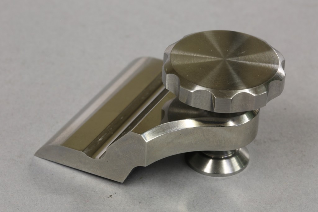
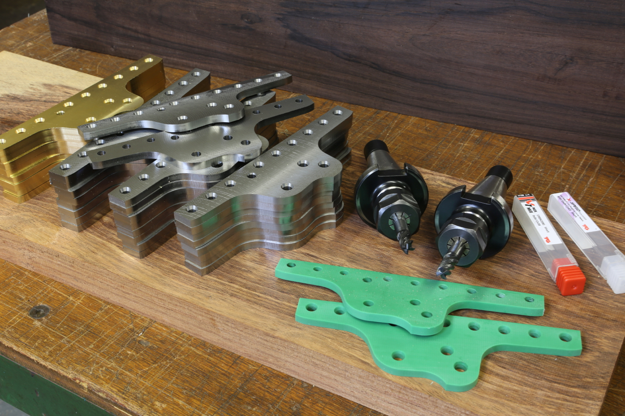
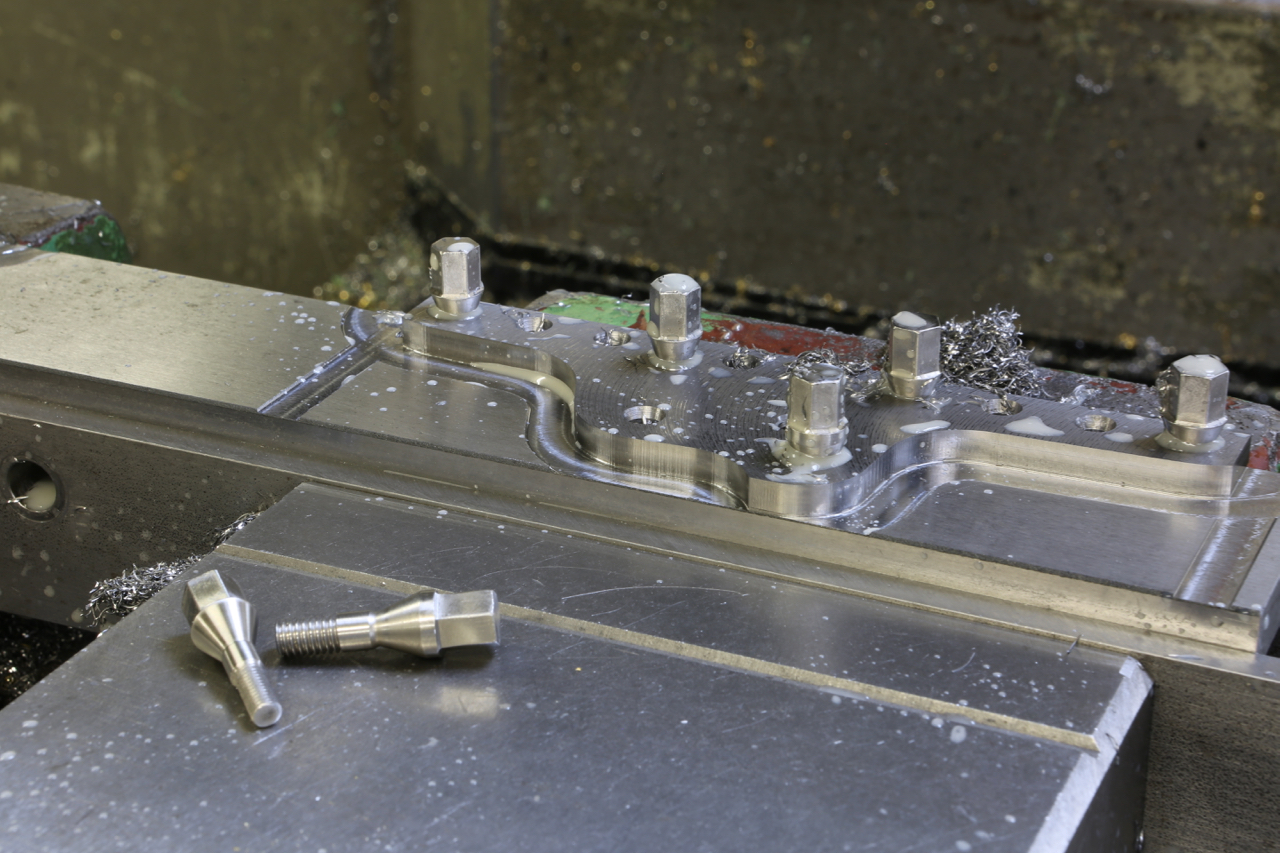
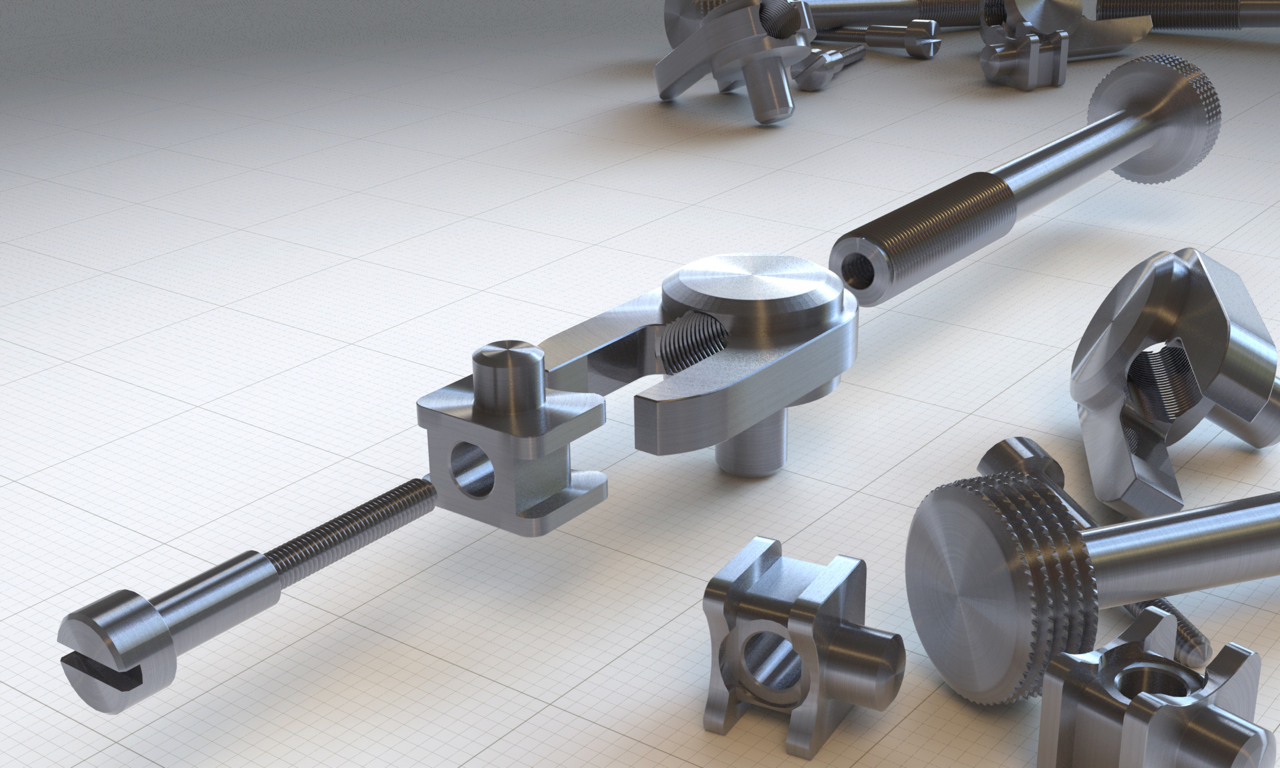
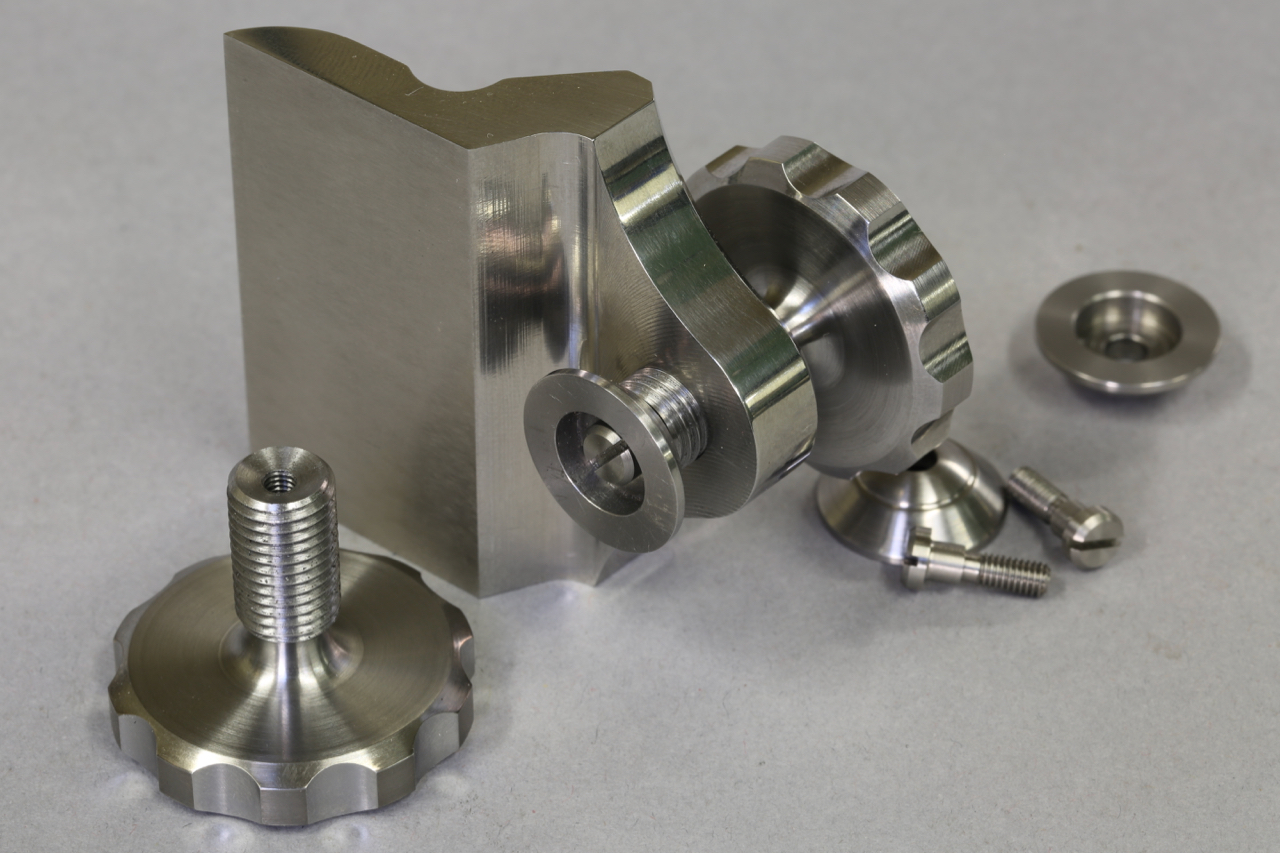
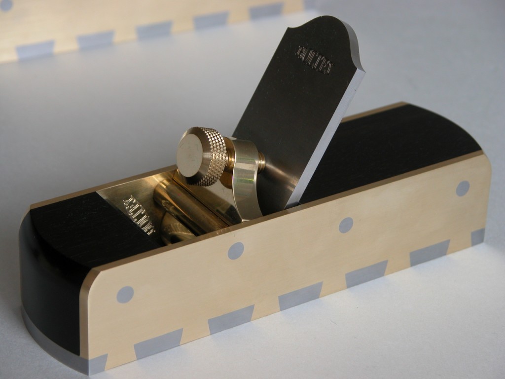
The photo below shows the swivel which is balled so it matches any irregularities whilst connecting with the blade. This is, like most of my design elements, my own innovation.
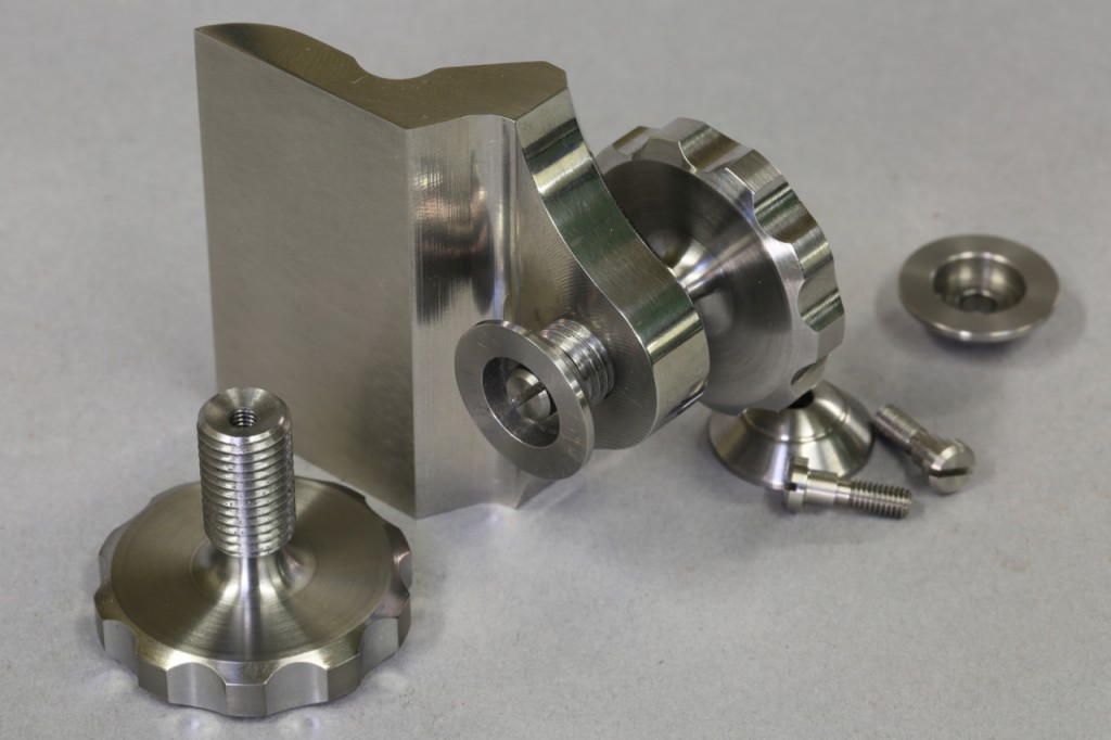
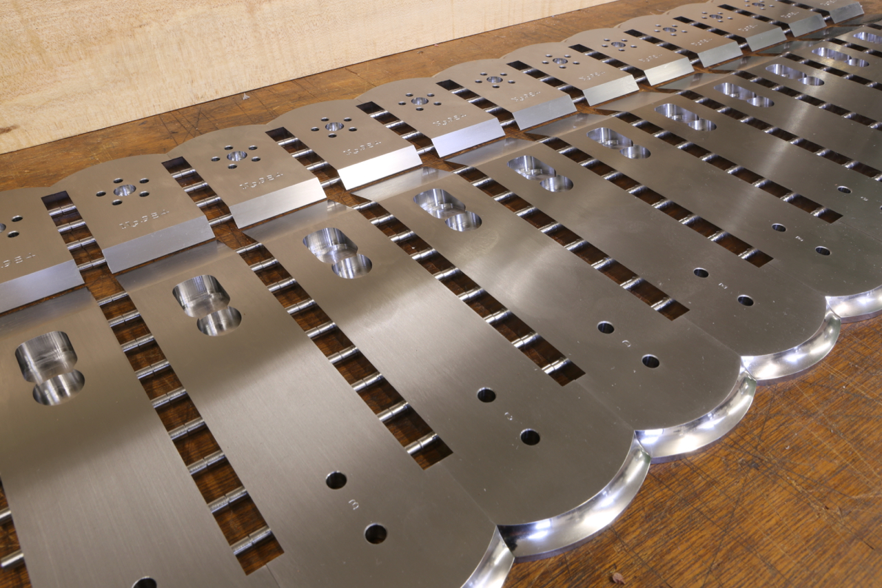
As you can see the lever cap (from my No 984 plane which is blogged here:http://www.holteyplanes.com/blog/category/no-984/, showing the machine working) is stepped/recessed so that it will carry a swivel. This is necessary with adjuster planes as the swivel shoe will bridge the adjuster holes in the blade. From my research it appears that I am probably the first pioneer to drop the chip breaker on bevel down planes. The first plane I made like this was the 11-s (see photo)
As the 11s has no adjuster drillings the lever cap was quite straight forward and less work. When I made the No 982 I was able to avoid the holes in the blade with the lever cap placement but it put some limitations on the design.
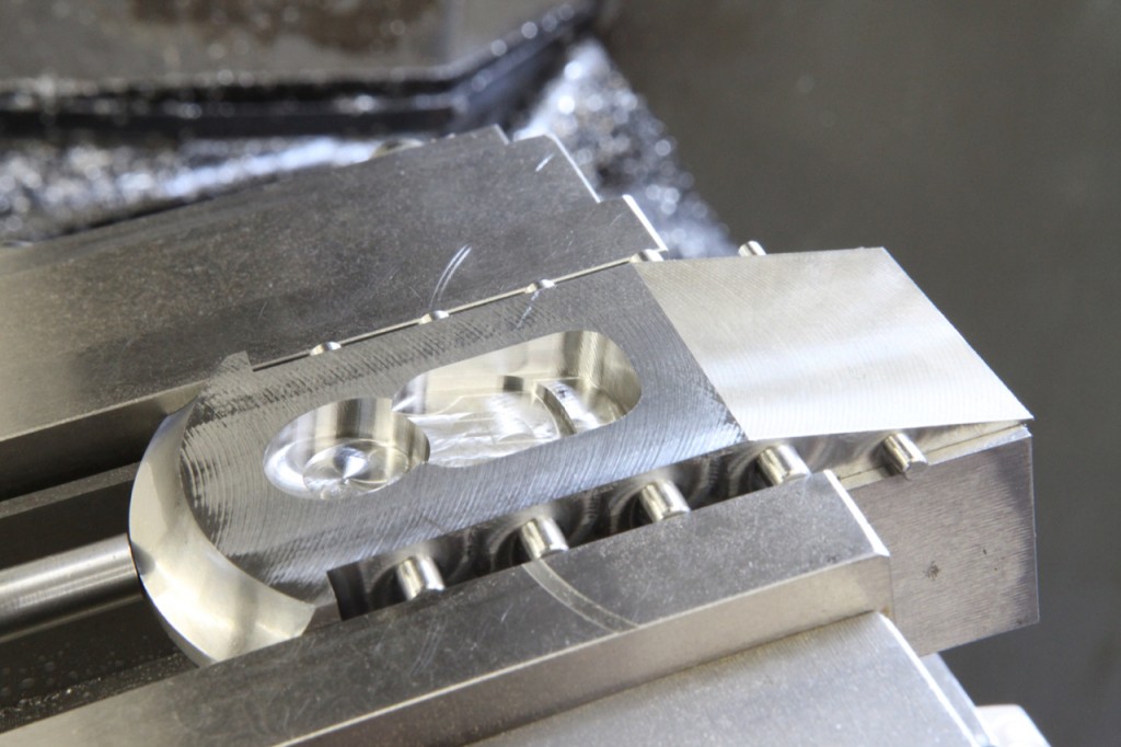
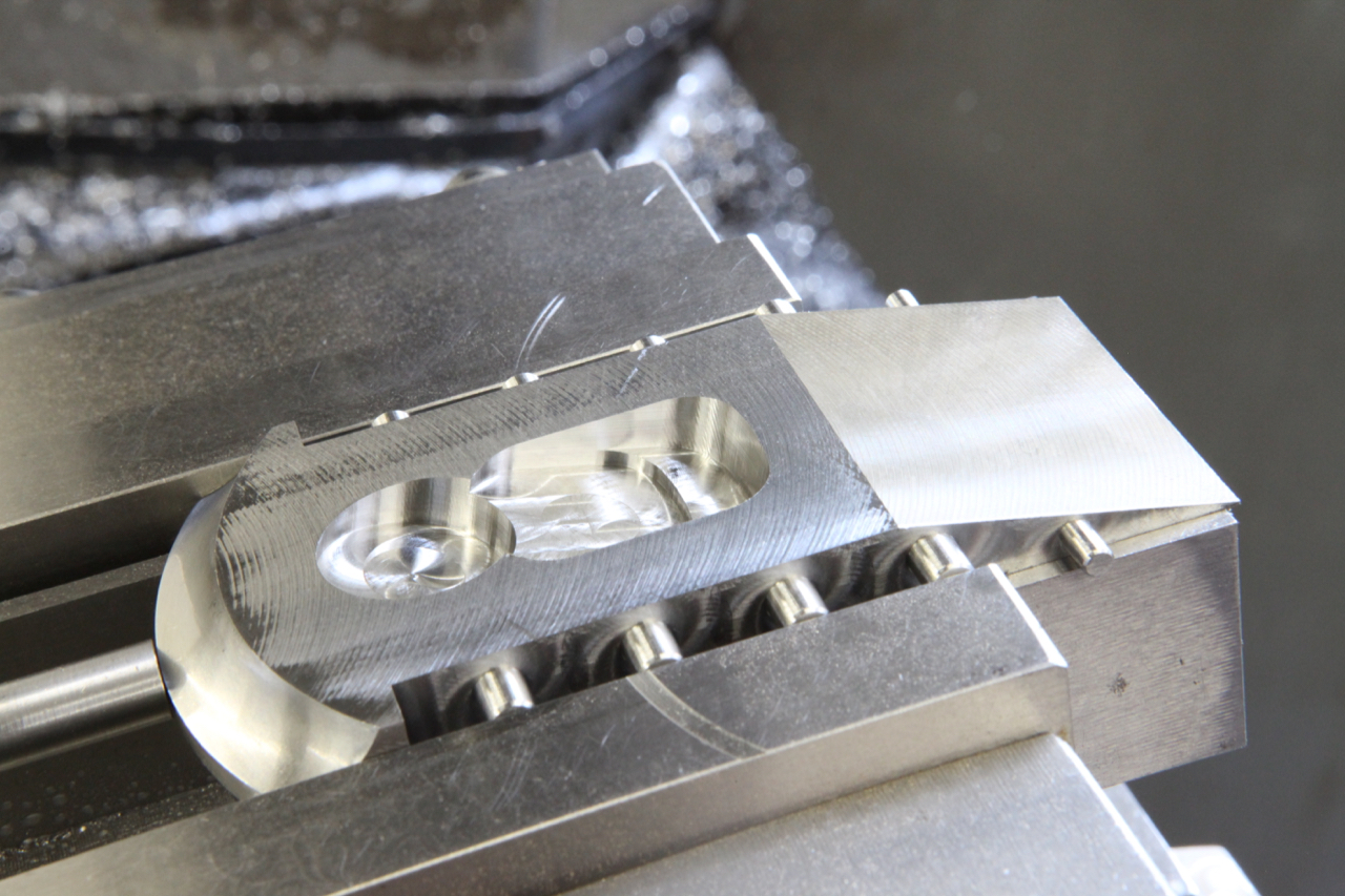
This is an example of the adjuster recessing in the No 983.
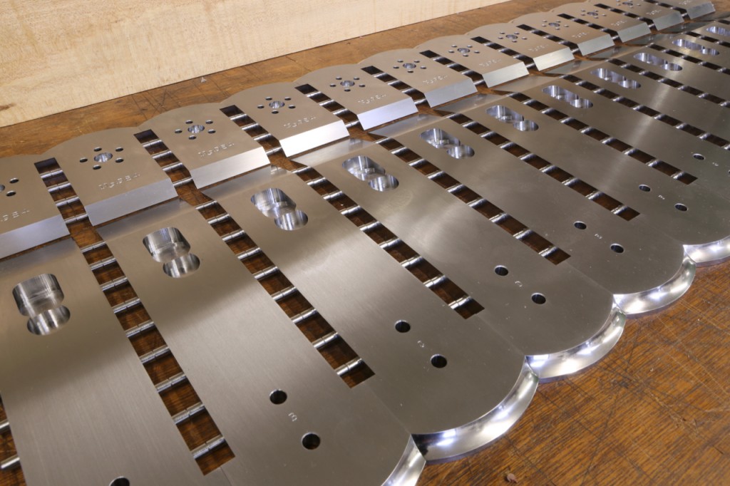
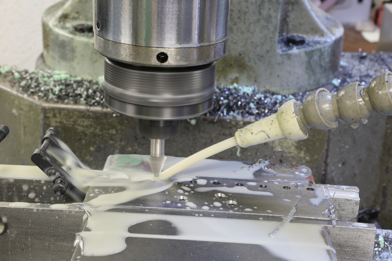
This is the bottom for the No 984 showing the adjuster recess.
In summary: to add an adjuster, both adjuster and plane have to be truly integrated. Of course the adjuster has to be made as well.