The last batch of A6 planes part 1
After receiving a commission for an A6 smoother I decided to make a batch of six. The A6 is probably the most time consuming of the infill planes (well perhaps the A7 is worse!). When using the designation A6 one should realise that my A6 is not to be compared with the Norris or any other plane of this type – it is made to a higher precision and has some innovations not seen in the original. This standard is beyond the scope of those without a tool room; I am not aware of any comparison. I work from a reasonably equipped tool room; not a production line. All work is done in house with the exception of heat treatment for the blades.
Although this model has been blogged before I am running it through again as this A6 is just that little bit more special. I always try to make the current plane better than the preceding one. Also these will be the very last Holtey A6 planes. For all my innovations and upgrades my work is veiled by the Norris history and I feel it is time to move on.
************************
The first part of starting the plane is to get the timber chosen and prepared so giving the wood some time to settle whilst making a start on the metal work.
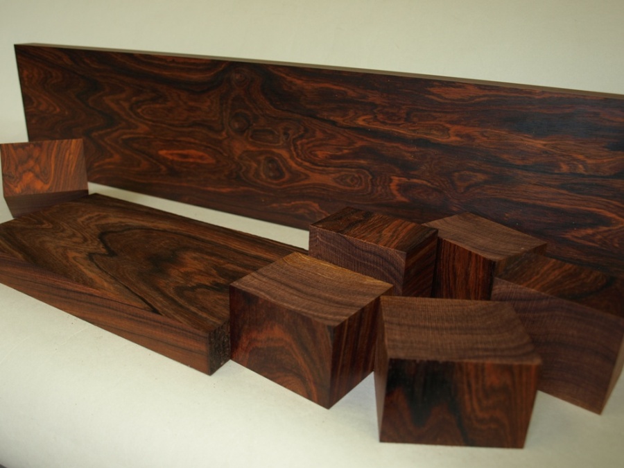
Here is a stunning piece of Cocobolo (Dalbergia Retusa) which was cut from a very nice log that I acquired from Timber Line a couple of years ago – thanks to a friend who spotted it on a visit there. This is the basic roughing out for the infill components.
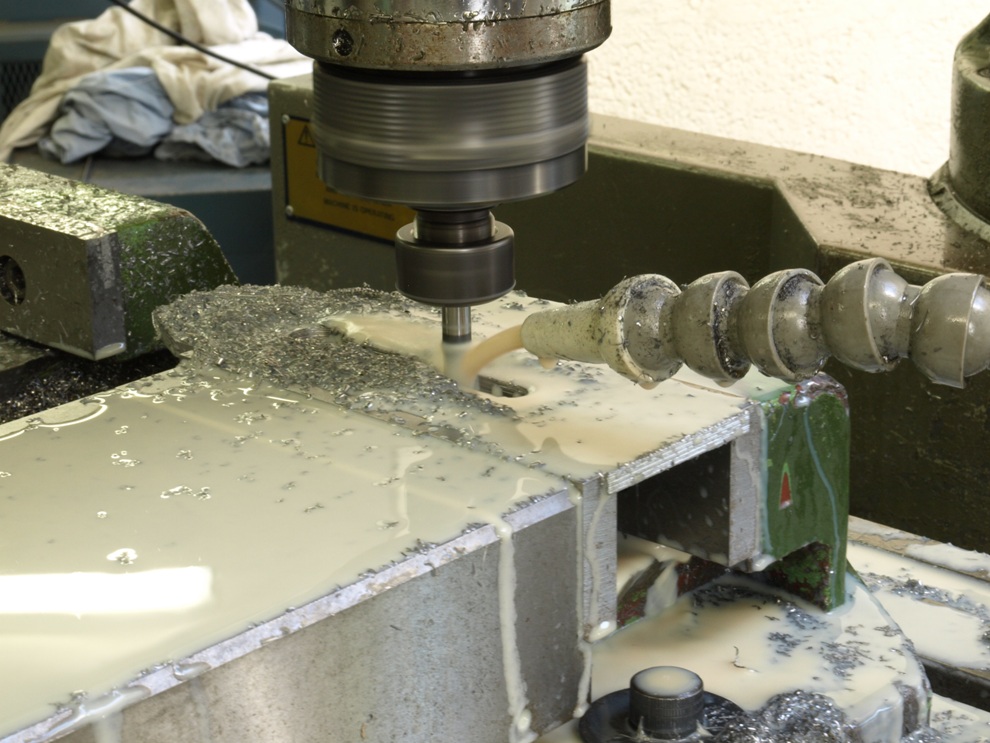
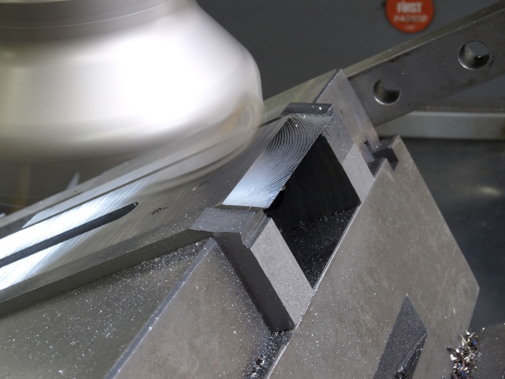
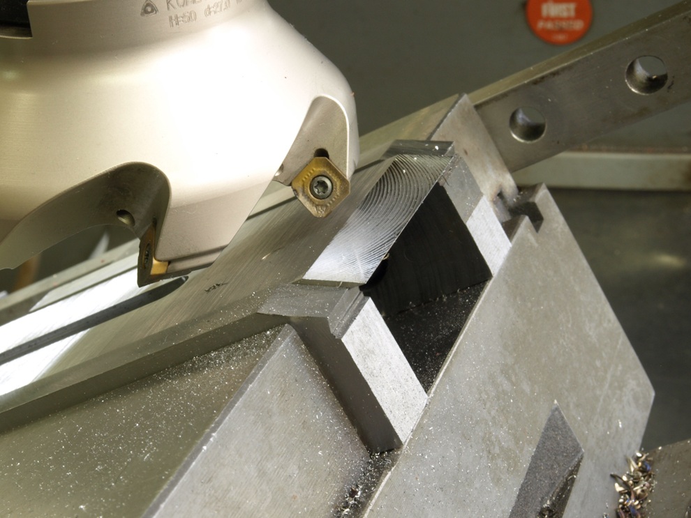
With the wood put aside to rest, a good starting point is the blades as they need to be sent away for the heat treatment. This shows the milling of the faceted end and slot.
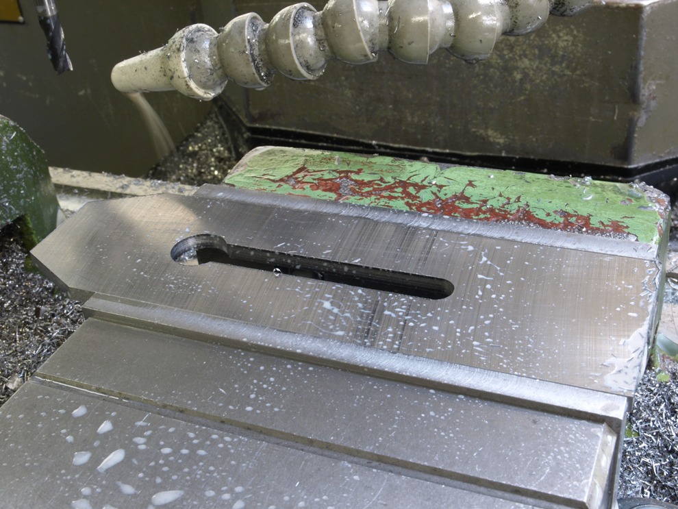
Work holding and stop for milling the bevel
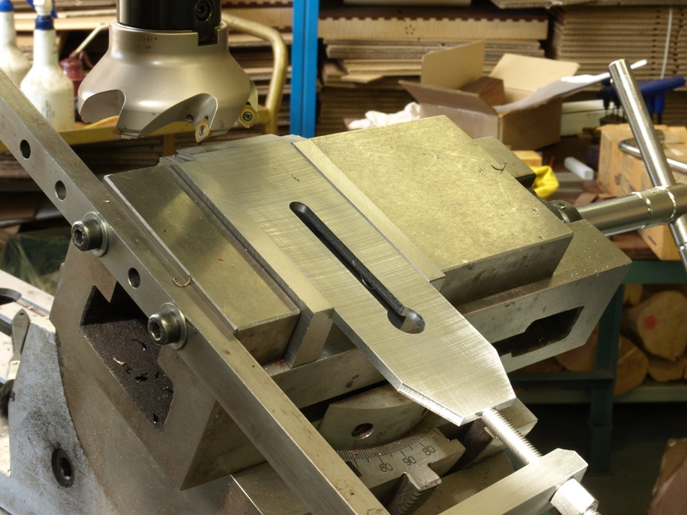
Now that everything is shaped and uniformed the bevel is then machined
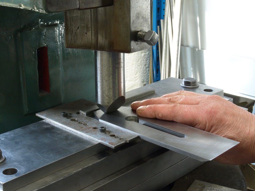
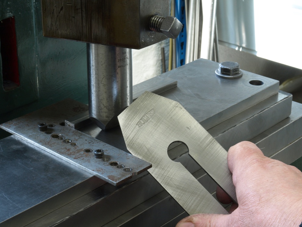
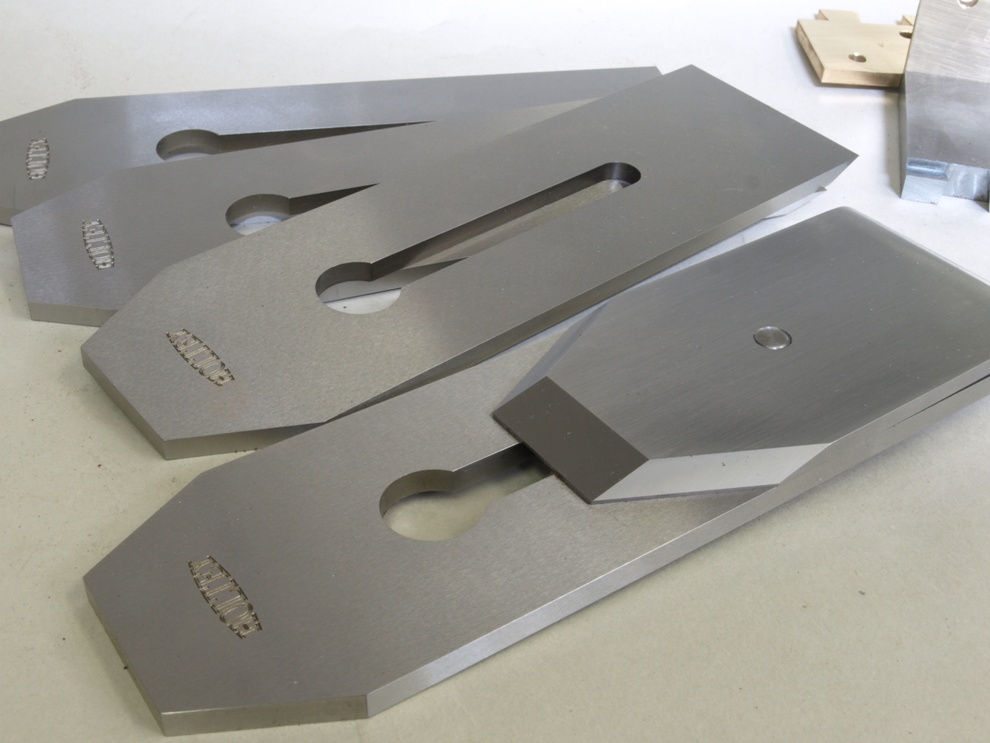
The last job is to stamp the logo before sending off for heat treatment.
With the blades back from the heat treatment I have precision ground them on all surfaces including edges. The picture shows the chip breaker which came from stock I made some time ago.
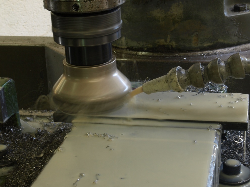
Bottoms. The material arrives as a black bar covered in scale. I have found that the easiest way to deal with this is to mill through the scale in preparation for surface grinding.
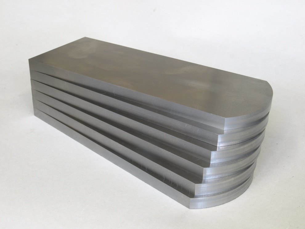
The bottoms are now in a good starting form, that is edges milled and top and bottom faces surface ground. These bottoms are heavier than normal as I felt a little bit of extra weight would work quite well on this plane.
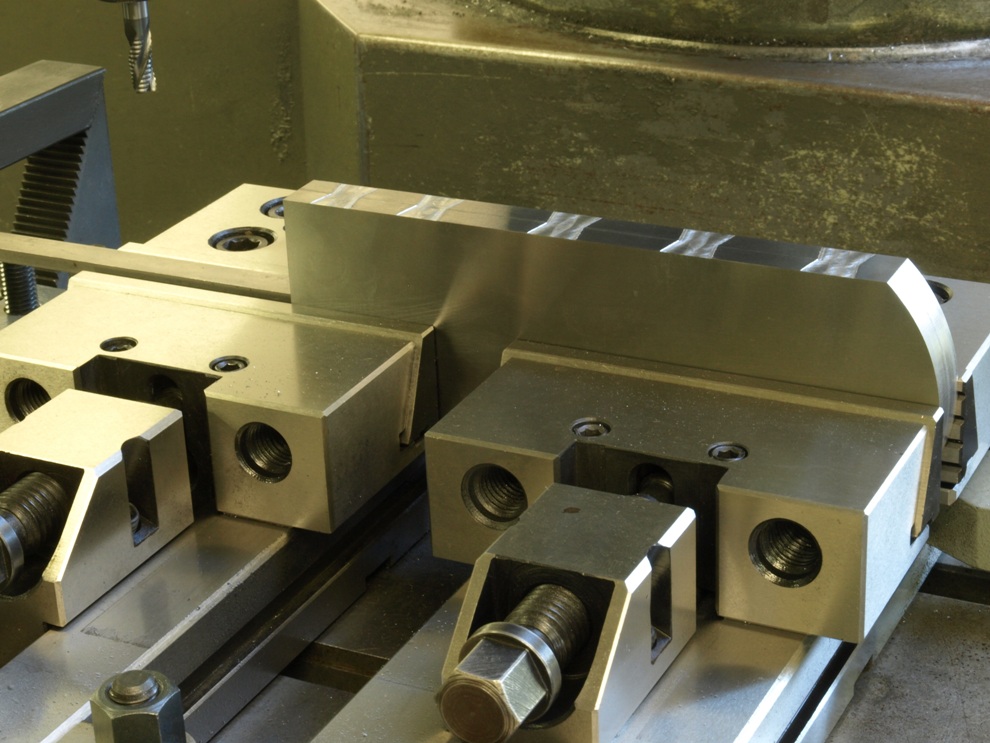
Setting up for the dovetail pins on the bottom. This picture shows the proving of the programme written for this procedure. For safety I am just etching the edge by a thou so I can see everything is in the right place and there are no errors. As this dovetail cut in the bottom is going to be compounded I can only work two bottoms at a time by putting them together top to top – this you can see from the etching and the finishing cut.
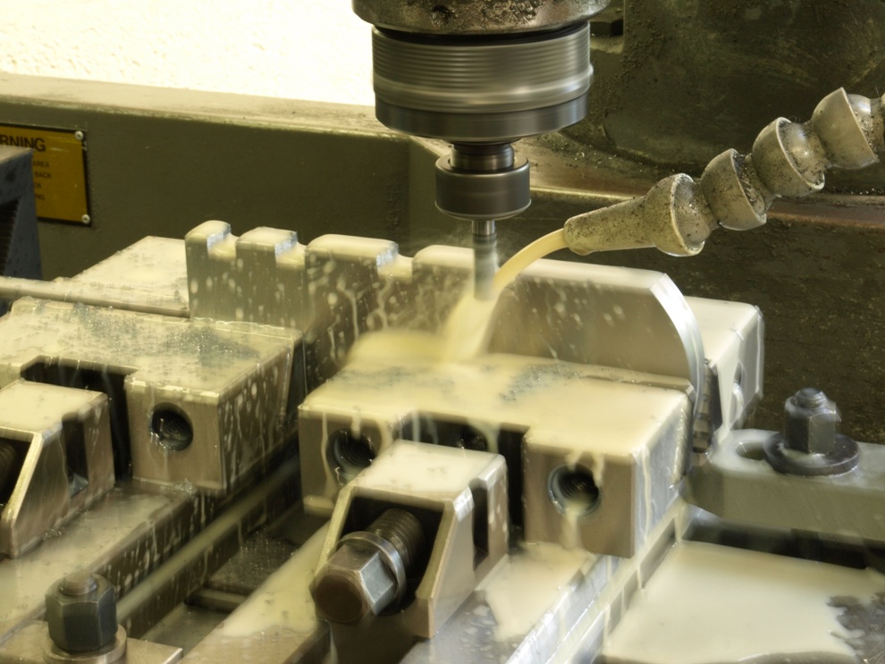
The first cut is done with a plain end mill cutter.
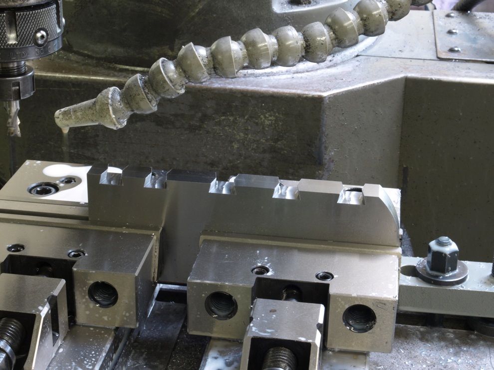
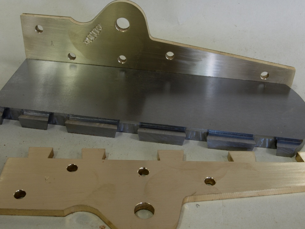
After the milling with the plain cutter is finished I need to go through a second time with a finishing cutter that has been ground with the dovetail form.
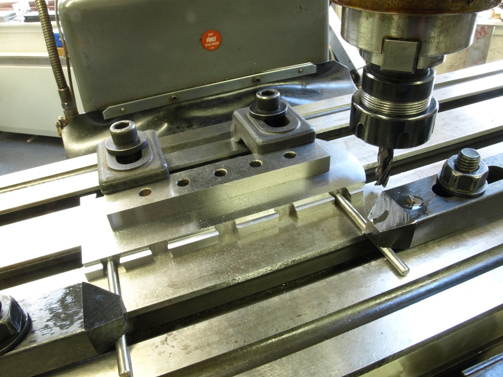
With the compound dovetailing finished the dovetails are machined down to produce a rebate which provides extra stability and strength.
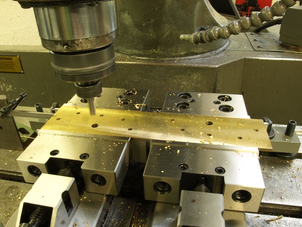
The sides are made from naval brass (CZ112) and always bought with an oversized thickness as the thickness required is never available. I have to mill down so I can finish at the required thickness. This picture shows the sides after this has been done and now the dowel and lever cap holes are bored in pairs which are folded together i.e. left and right hand side together.
During my research of Scottish and English dovetailed planes I have found that a common thickness of the plane sides is 5/32″. Brass plate is usually available in 1/8″ or 1/4″ thicknesses. I think that 1/4″ is too thick. All my infills (except 11sa) are finished just above 5/32″.
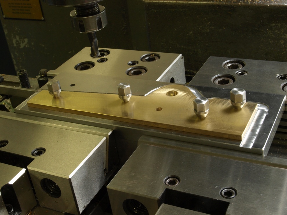
After the drilling the two brass sides are separated by a band saw cutting close to the profile and are then fixed to a holding plate via the dowel/rivet holes with jig screws. This enables the profile to be milled. In the case of steel I need to separate the two sides by routing through with the milling machine as the steel does not lend itself to band sawing.
Obviously the bottom is yet to have its mouth and frog but for the picture just checking for fit.
Karl
Thanks for posting.
Wonderful work as always.
Are you ceasing to make infills or just Norris copies?
Scott
Comment by Scott MacLEOD — August 1, 2011 @ 7:12 pm
Hi Scott
I have been trying to move away from infill planes but it is very difficult as there will always be a demand. Even though the designs of infill planes that I have been using are representations of Norris planes there is a lot more engineering gone into these than the original counterparts. If I were to make a true copy then there would be a lot less work for me!
My version of the A13 has been ergonomically and aesthetically adjusted and the most noticeable of these features is the front bun. People now use this feature as a reference to the A13, whereas it was not on the original. All those smoothers using an A13 style are using my A13 as the benchmark.
If I am to make more infills it is time to break away from the Norris style and design for myself. Just wish I had more time to play around with designs.
k
Comment by admin — August 3, 2011 @ 9:19 am
I’ve been using one of these final Holtey A6 smoothers for the past few weeks, and what a magnificent instrument it is!
I bought the A6 to use alongside a very nice pre-war, Norris A1 panel plane that I’ve used for the past twenty years. Although I’ve gradually been moving away from infill planes, ironically to take advantage of Lie-Nielsen’s A2 irons. I say ironically because I believe the pioneer of A2 steel for plane irons was actually Karl Holtey himself! Furthermore, Karl has kindly agreed to make me a couple of A2 irons for my Norris A1, so that I can maintain sharpening and usage consistency between both planes, and move back to the pleasure of infills.
It’s probably worth saying a few words about Holtey plane irons. I first came across them many years ago, and used his early A2 and S53 irons in my tuned up Stanley Bedrocks. They were (and are) fantastic blades, and I still use the S53 irons when working in highly abrasive teak on boat building projects, as although it’s demanding to hone it goes an awfully long way between sharpenings. I understand that Karl used to contract out the final finishing of his irons, but now surface grinds in-house. I can certainly see a difference in the machining signature on the irons that came with the A6 compared with the earlier Holtey irons. The early ones were very, very good; but these latest irons are beyond flawless. I took two spare irons with the A6, one I’ve given a 20 degree back bevel for particularly confused grain, and the other two I’ve honed with a secondary micro bevel at 38 degrees. Even though I use the A6 strictly as a smoother I still use a very shallow camber, I know most people would straight grind with a tiny radius at the corners but I prefer a feathered edge. I find a camber of about 0.15mm, then flattening the centre on a 30,000 Shapton stone, gives a nearly two inch wide shaving at one thou or less that imperceptibly feathers away to nothing at the edges. It delivers a quite beautiful result that can take oil or wax with no further finishing. Incidentally, Shapton stones make a great partner for Holtey A2 irons. I normally hone plane irons to an 8,000 grit, but a Holtey iron deserves an extra something, so I take the back of the iron and the secondary bevel all the way to 30,000 grit, which is about half a micron.
Karl delivers his irons ground at 25 degrees, I’ve three or four honings to go before I’ll need to regrind, but when I do I plan on increasing the primary grind angle to 28 degrees or even 30 degrees. If that produces anything dramatically good or bad I’ll report back!
Moving on to the plane itself, although relatively small it plants itself on the wood with real authority. No surprise as the A6 weighs in at 2.925 kilos, mainly due I guess to the extra heavy sole which is about 8.5mm thick, I believe this is the heaviest sole Karl’s ever used in a Norris inspired smoother. For comparison my Norris A1 panel plane isn’t that much heavier at 3.550 kilos. This is about as heavy as I’d want a smoothing plane to be. In my opinion bench planes hit a sweet spot at about 3.0-3.5 kilos, any lighter and they can’t adopt an authoritative stance on the work piece, much heavier and they’re becoming too awkward to control with finesse or use for an extended period of time.
Handling such a weighty tool puts real emphasis on the handle design, and here unfortunately the A6 doesn’t quite score full marks. Not Karl’s fault, it’s just a limitation of the original design. Most significantly the A6′s extended side cheeks prevent the index finger being extended straight ahead, although I imagine this brings a compensating benefit of better support for the iron. There’s also a small “horn” on the top of the handle, personally I’d prefer if this were extended by another 10mm, as you could then reference the plane’s aspect by feel without looking at it. I appreciate these horns often get damaged, although my Norris is now well over 80 years old (and I’ve used it regularly for a quarter of that period) and it has managed to avoid having the longer horn chipped off.
I’m glad to say one other undesirable design feature of some Norris infill planes was happily absent in the Holtey A6. I’ve noticed that some (not all but some) planes with the Norris adjustor have a very finicky lateral adjustment, and advancing or withdrawing the iron can cause the lateral adjustment to jump by a fraction. In fact this is why I don’t use an original Norris A6 alongside my Norris A1, I’ve just never found one for sale that could hold the lateral adjustment with absolute precision, I’ve handled a few that could but unfortunately they weren’t for sale. When taking ultra fine cuts the exactitude of the lateral adjustment is critical. I was especially worried because I’d read an article by David Charlesworth where he built an infill smoother from a Shephered kit, and incorporated a Holtey lateral adjuster and encountered this exact problem. Happily this A6 is nothing less than perfect, I can set a tiny bias in the lateral adjustment, withdraw the iron completely, advance it again, and the previous cut is still perfectly registered. Why Holtey planes and some Norris planes are immune, but other Norris planes suffer is a mystery that I’d love to have explained. It’s by no means a statistically robust sample, but from the thirty or so Norris planes I’ve handled I’d guess that the lateral adjustment problem is mainly confined to the later planes.
Karl told me that the sole of his A6 would be flatter than I could measure. Not having NASA’s resources I was inclined to believe him, but none the less I set up a experiment which even my best fettled planes couldn’t pass. I set up a Moore & Wright straight edge diagonally across the sole, resting on five scraps of wafer thin cigarette paper (too thin for me to consistently measure), I couldn’t slide any of them free, all five were equally pinched between the sole and the straight edge. I don’t know if this has any significance, and I’m sure it would be derided in engineering circles, but it sure impressed me!
All in all this is a quite exceptional tool, one that will give me many years of inspiration and pleasure as well as removing any excuses for not achieving flawless results! Consequently I’d like to extend my thanks and congratulations to the astonishing dedication of its maker, Karl Holtey, the creator of the finest planes the world has ever seen.
Comment by Gary — September 6, 2011 @ 5:38 pm
Hi
Thank you very much for your time and trouble in posting this. It is very interesting.
The reason for the fault you mention about the loss of lateral position is due to the poor relationship between the lever cap and the bed or it could be inconsistencies in blade and chip breaker consistency. In other words lack of precision.
k
Comment by admin — September 6, 2011 @ 10:27 pm